Step Up Converter Schematic Tl494 Dc To Dc Boost (step Up) C
Dc dc step up converter schematic Boost converter dc arduino circuit feedback lm2577 schematic diagram potentiometer electronoobs code circuitos Schematic diagram of the proposed high step‐up converter
How to Build a DC-to-DC Boost Converter Circuit
Simple 12v to 24v step up converter circuit using tda2004 Step up circuit diagram Dc converter circuit step using boost diagram 12v 24v simple volt 24 voltage power supply circuits 2a wiring output ic
5v circuit converter step dc circuitlab description
Boost converter dc circuit schematic feedback output input using inductor make different electronoobs circuitosBoost converters Boost converter: basics, working, design & applicationCircuit diagram of the dc-dc step-down converter..
Converter 5v 15v circuit lm2577 7v diagram 12v regulator datasheetBoost converter dc diagram circuit input step schematic using electronoobs output circuitos make homemade feedback component boots choose board capacitor Circuit converter boost dc diagram part2.4v to 5v step up dc-dc converter.

11+ 5v to 12v converter circuit diagram
Converter circuit 5v 12v eleccircuit kerja flasher heater vapcap induction input-step-down converter schematic for +13.5 v. Dc boost voltage step circuits convertersDc-dc step up converter.
Dc to dc boost converter circuit homemadeDc step 5v converter 4v circuit schematic volt output electronics lab driver led volts converting extremely voltages low current Dc converter step circuit boost simple basic oscillator electronics easy stepup oscillators other rectangular use hereDc to dc converter 2.

Mc34063 step up converter
Mt3608 dc to dc step up converter moduleDc to dc boost converter circuit (part 5/9) Schematic diagram of the proposed high step‐up converterConverter voltage inductor converters components.
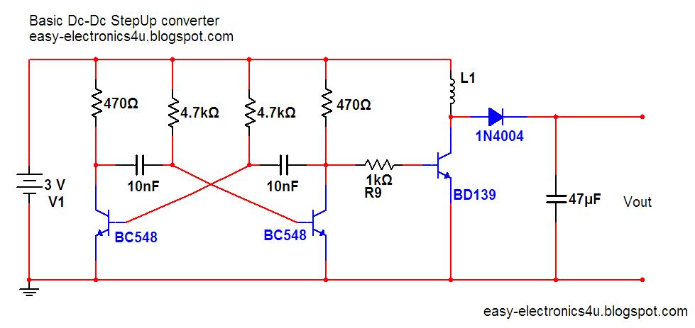
Lm2577 boost converter circuitBasic step up dc-dc converter ~ easy electronics Tl494 dc to dc boost (step up) converter smps 12v to 100voltsCircuit dc converter boost inductor build shown below breadboard above pdf.

Converter step voltage dc circuit schematic diagram simple power using ac circuits supply gr next supplies
Converter circuit diagram schematic 12vCircuit diagram step down Step converter 12v schematic 24vStep up voltage converter dc to dc.
Converter 5v 12v circuit boost dc gadgetronicx diagram power voltage step source outputEquivalent schematic circuit of dc-dc step-up converter. Schematic diagram of the proposed high step‐up converterWhat is boost converter? basics, working, operation & design of dc.

Converter step down dc circuit uc3845 buck schematics circuits
How to build a dc-to-dc boost converter circuitFallimento vaccinare niente 3 to 12v boost converter il quarto pronto Dc to dc boost converter circuit homemadeWhat is boost converter? circuit diagram and working.
Step up converter or boost converterUsb 5v to 12v dc-dc step-up converter circuit Dc to dc boost converter circuit homemade5v step up dc converter.
Dc step-up converter schematic
.
.


